3D Printing Infill Patterns: Gyroid, Honeycomb & Grid Compared
What Is Infill in 3D Printing?
Infill is the internal structure of a 3D printed part, built between the outer perimeter walls to provide strength and stability without making the part solid. Adjusting the pattern and density lets you control weight, durability, and material usage, which ultimately impacts production turnaround and costs. As demonstrated in a study by Agus Triono, Mahros Darsin, et al., infill patterns significantly influence the mechanical properties of 3D printed parts, including compressive strength, tensile strength, and flexural strength,
In This Guide
- Learn how infill works, why it matters, and how it affects part performance.
- Compare common patterns like grid, honeycomb, and gyroid, and see when to use each.
- Understand the relationship between density, weight, and material efficiency.
- Match infill choices to your part’s functional requirements and production goals.
For our complete guide to 3D printing, read our blog: Your Guide to On-Demand 3D Printing
Learn more about Simple Machining’s 3D printing services.
What Are the Different Infill Patterns in 3D Printing?
Each pattern has unique mechanical properties and print characteristics. For instance, honeycomb and gyroid patterns take slightly longer to print but offer superior strength compared to a simple grid. The choice of pattern depends on functional requirements, part geometry, and intended use.
If you’re designing for end-use, our engineers can help select the most suitable infill pattern based on your CAD model and performance needs. You can reach out here.
Grid:
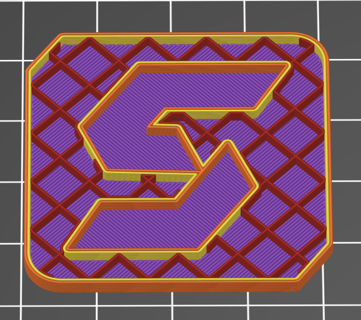
Infill pattern: Grid
A simple square pattern that offers balanced strength and print speed. It’s easy to slice and works well for most general-purpose parts. Because of its even distribution of material, grid infill provides predictable strength in multiple directions, making it a go-to choice for prototypes and functional parts.
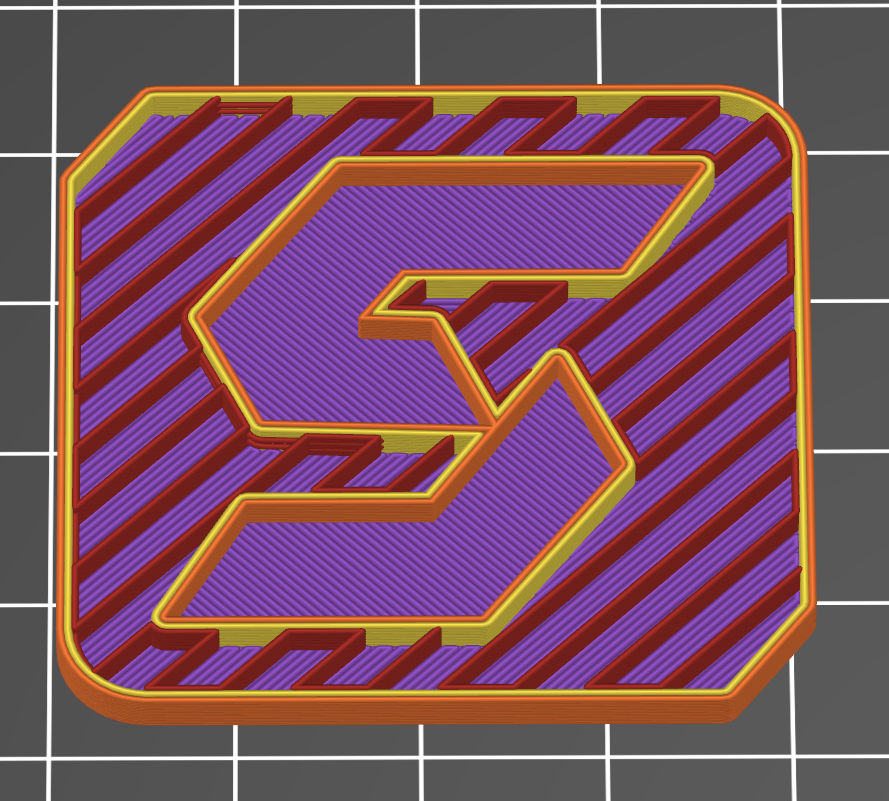
Rectilinear:
Infill: Rectilinear
A straightforward infill made of straight, parallel lines that alternate direction each layer. It prints slightly faster than grid because it uses fewer extrusion moves and avoids overlapping paths. However, unlike grid, it doesn’t create a fully connected lattice within a single layer, so the strength is somewhat lower in diagonal directions. Rectilinear works well for quick prints or parts where speed and simplicity outweigh the need for uniform multi-directional strength.
Aligned Rectilinear:
Infill: Aligned Rectilinear
Similar to the standard rectilinear pattern but aligned to the part’s principal axes for better directional strength. This pattern offers consistent stiffness and load resistance along the X and Y directions, making it well-suited for parts that experience forces primarily along these axes. It’s also easier to slice and print than more complex patterns.
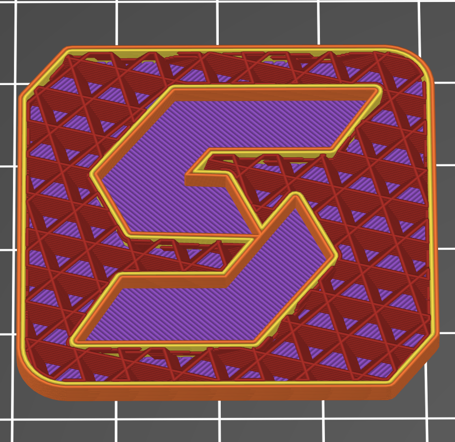
Triangular:
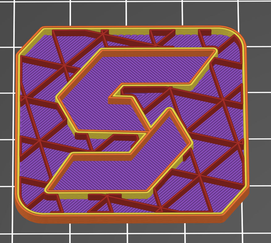
Stronger than grid patterns, especially for thin walls or parts requiring higher stiffness. The triangular geometry distributes load efficiently and resists deformation under pressure. The tradeoff, however, is that it takes a bit longer to print.
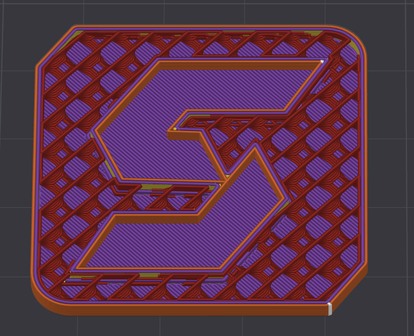
Honeycomb:
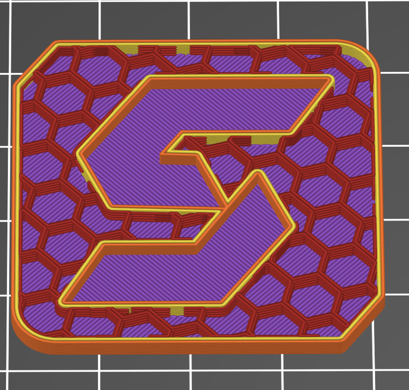
Infill: Honeycomb
Lightweight yet strong, honeycomb patterns excel in applications where weight reduction is critical. Their natural geometry mimics structures found in nature, offering excellent strength-to-weight performance. However, they can take longer to slice and print compared to simpler infills. Honeycomb is most effective in rectangular parts where the internal volume is a major percentage of the overall model.
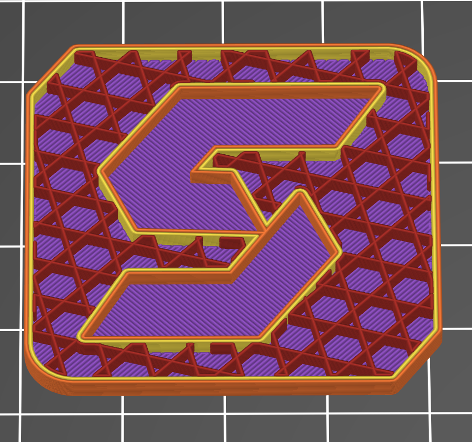
3D Honeycomb:
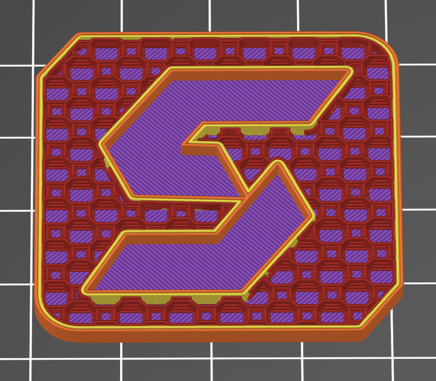
Infill: 3D Honeycomb
A volumetric honeycomb pattern that extends the traditional 2D hexagonal structure into three dimensions. It provides superior strength and stiffness by distributing loads evenly throughout the part. This pattern is ideal for parts needing high strength-to-weight ratios and excellent energy absorption, commonly used in aerospace and automotive applications.
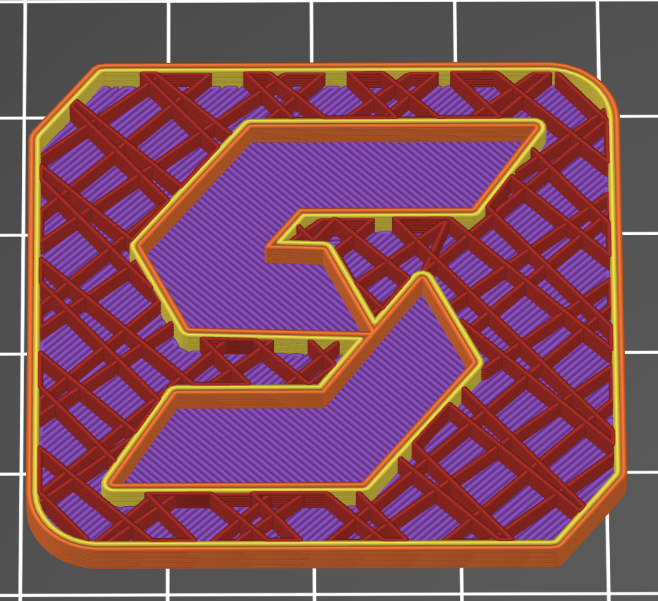
Gyroid:
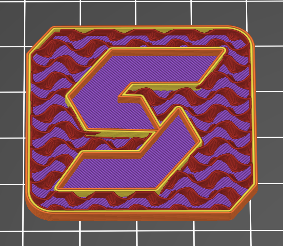
Infill: Gyroid
Offers excellent strength in X-Y directions and smooth internal surfaces, making it ideal for parts with complex stress profiles. The continuous, wavy structure can also improve impact resistance. Gyroid infill tends to be more material-efficient than dense grid patterns while still maintaining higher overall strength.
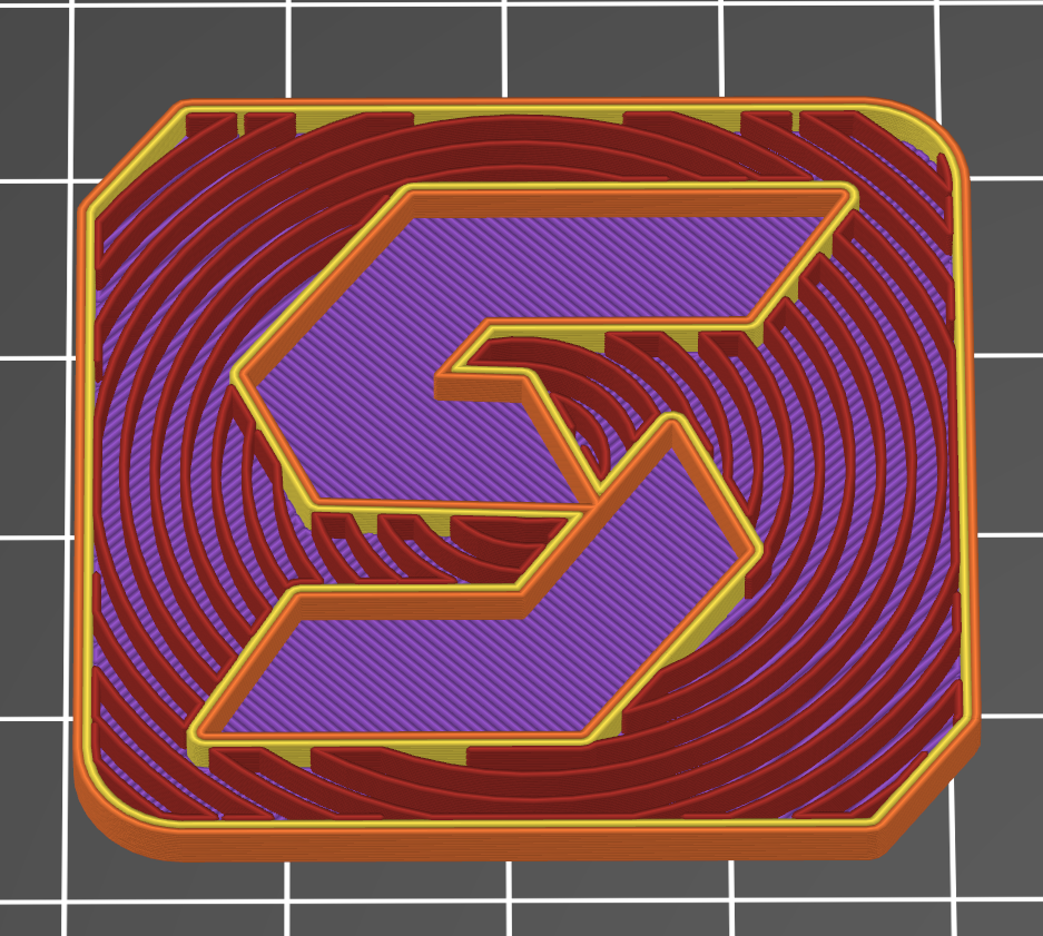
Concentric:
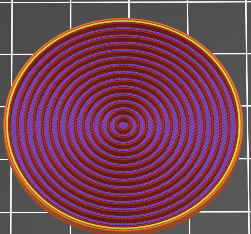
Infill: Concentric
Great for round parts or those that need consistent strength along curved surfaces. This pattern follows the outer shape of the part, reducing the chance of weak points in circular or organic designs. It’s often used in aesthetic pieces or components that don’t require maximum internal rigidity. This also has a reduced chance of piercing the outside surface, creating visual deformities.
Hilbert Curve:
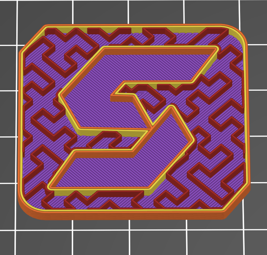
Infill: Hilbert Curve
The Hilbert curve infill follows a continuous, space-filling fractal path that creates a dense, interconnected internal structure. This pattern offers excellent strength and impact resistance while maintaining good flexibility, making it suitable for parts that experience multidirectional stresses or require energy absorption. Though more complex to print than basic patterns like rectilinear, the Hilbert curve balances material usage and mechanical performance effectively, especially in components where uniform load distribution is critical.
Archimedean Chords:
Infill: Archimedian Chord
This pattern uses curves based on Archimedean spirals or chords to create smooth, flowing internal structures. It balances material use with structural support, providing good flexibility and resistance to deformation. It is useful for parts requiring gradual stress distribution and vibration damping.
Octogram Spiral:

Infill: Octogram Spiral
An intricate spiral pattern based on an eight-pointed star (octogram) shape. It offers strong directional support with a unique aesthetic and mechanical performance, providing balanced strength along multiple axes. This pattern suits parts that face complex loading or need a distinct internal structure for flexibility. We commonly print this infill for clients looking for TPU parts.
Cubic:
Infill: Cubic
A three-dimensional lattice pattern forms a grid of small cubes inside the part. Cubic infill offers excellent isotropic strength, meaning it distributes loads evenly in all directions. It’s a popular choice for functional parts requiring balanced stiffness and durability without excessive weight. Cubic patterns also tend to print efficiently with good material usage.
Stars:
Infill: Stars
An infill pattern composed of star-shaped nodes connected by lines, creating a network that provides strong local support while minimizing material. Star infill offers good resistance to deformation and can improve impact absorption. This pattern is useful for parts that need targeted reinforcement or enhanced energy dissipation, often in applications requiring some flexibility combined with strength.
Line:
Infill: Line
A straightforward pattern of parallel straight lines, usually printed in alternating directions between layers. Line infill is fast and uses minimal material but offers limited mechanical strength, making it best for visual prototypes or parts where internal support isn’t critical.
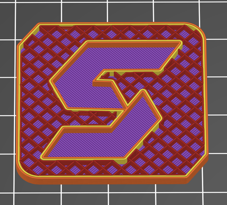
Cross Hatch:
Infill: Cross Hatch
Formed by two sets of parallel lines intersecting at right angles, creating a grid-like structure inside the part. Cross-hatch infill improves strength and rigidity compared to single-direction line patterns while still being relatively quick to print. It’s a common choice for functional parts needing balanced support.
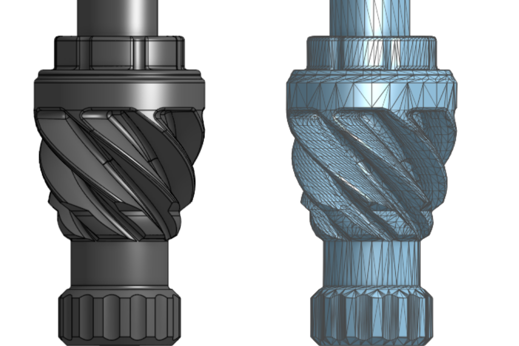
Gyroid Infill: When to Use It and How It Performs
Gyroid is a continuous, triply periodic surface that fills internal volume without intersecting itself, and it has become the default recommendation for end-use parts in FDM 3D printing that need balanced strength in all directions. It is the most-searched pattern after grid, and for good reason: it offers near-isotropic mechanical behavior and a clean toolpath that most modern slicers handle well.
The tradeoff is print time and acceleration sensitivity. The decision logic below covers when gyroid earns its longer print, and when a simpler pattern is the better choice.
How Gyroid Compares to Honeycomb and Grid
Gyroid distributes load more evenly across the X, Y, and Z axes than either honeycomb or grid. Grid infill builds in-layer stiffness with two perpendicular line sets per layer, but stiffness varies with load direction and shell thickness. Honeycomb, especially 3D honeycomb, excels at strength-to-weight in rectangular volumes, but its hexagonal columns favor compression along one axis.
Gyroid's curved, continuous structure has no same-layer crossings. That avoids the raised intersections that can cause nozzle scarring on grid infill at higher flow rates, an issue covered in our rectilinear vs grid infill guide. For multidirectional loads, gyroid is the strongest general-purpose option in the FDM toolkit.
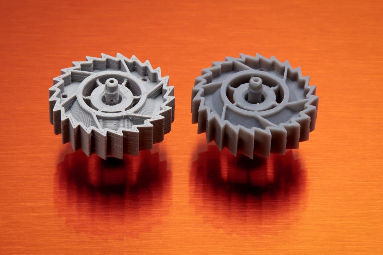
Print Time and Material Tradeoffs
Gyroid is typically 5 to 15 percent slower than grid at the same density. The reason is the toolpath: continuous curves require many small acceleration changes, which printers without input shaping handle inefficiently. Well-tuned machines lose less time than older or hobbyist hardware.
Material use is often lower than grid at equivalent strength. Because gyroid spreads load isotropically, you can usually drop a few points of density and keep the same functional performance. On a multi-part run, that adds up across spool consumption and machine hours.
When to Choose Gyroid
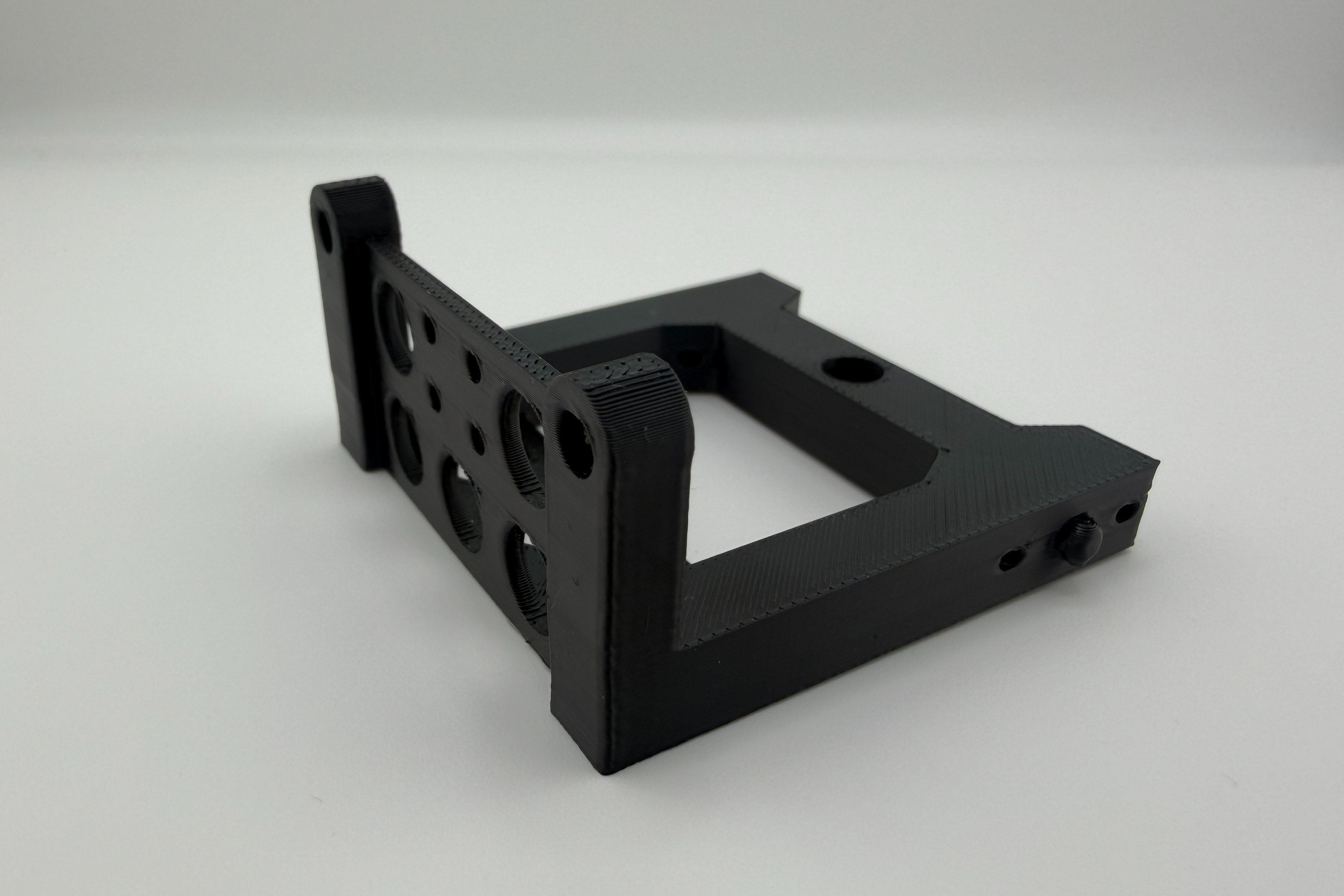
Reach for gyroid when the part will see multidirectional, dynamic, or vibration loads. Examples include brackets and mounts in motion systems, drone frames, end-of-arm tooling, enclosures that get handled in service, and any production part where one orientation cannot be guaranteed in use.
Skip gyroid when the part has broad flat top surfaces and skin pillowing is the failure mode being managed. Rectilinear or grid provides more predictable support directly under top layers. Skip it on visual-only prototypes where print time is the constraint and load is irrelevant. And do not use gyroid as a substitute for adequate wall thickness, since perimeters and shells dominate stiffness more than the core pattern in most failure modes.
Recommended Density and Settings for Gyroid
For visual prototypes, 15 to 20 percent gyroid is enough to support top layers and keep weight down. For functional prototypes that will be handled and stress-tested, 25 to 40 percent is the working range. For end-use parts under load, 40 to 60 percent paired with 3 or more perimeters delivers a substantially stronger envelope than thin walls with high-density infill.
If your printer is acceleration-limited, drop infill speed by 10 to 20 percent to keep the toolpath clean and avoid surface scarring. Pair gyroid with wall thickness changes before raising density past 60 percent, since shell strategy returns more strength per gram than core density alone.
learn more about our FDM 3D Printing Services
How Does Infill Density Affect Strength in 3D Printing?
Infill density is the percentage of a part’s internal volume filled with material:
10–20% → Best for light prototypes or visual models where strength is not critical. Produces the fastest print times and uses the least material.
30–50% → Suitable for functional prototypes or parts under moderate stress. Balances strength, weight, and print time.
60–100% → Provides maximum strength for tooling, fixtures, or load-bearing components. Used when durability is the top priority.
The relationship between infill density and part strength is not strictly linear. Doubling density does not always double the strength, and beyond a certain point, additional material may add unnecessary weight without meaningful performance gains. Choosing the right density means balancing strength requirements with production costs.
When working with high-performance materials like nylon, carbon-fiber composites, or metals, infill density settings can be fine-tuned to maximize both mechanical properties and efficiency.
When to Choose Specific Infill Settings for Your Parts
Selecting the right infill settings depends on the part’s intended application:
Prototyping: Lower densities (10–20%) with fast-printing patterns reduce cost and lead time while maintaining visual accuracy.
Functional End-Use Parts: Medium to high densities (30–70%) with structurally strong patterns like honeycomb or gyroid deliver durability without excessive weight.
Tooling and Fixtures: High-density infill (70–100%) ensures dimensional stability and resistance to mechanical stress.
Lightweight Components: Low-density infill paired with gyroid or triangular patterns can maintain structural integrity while minimizing weight.
As a rule of thumb, low-volume production and on-demand manufacturing projects benefit from tailored infill strategies. By customizing density and pattern, you can optimize each part for its functional requirements while keeping production costs in check.
Key Takeaways:
- Infill settings—both pattern and density—directly impact weight, strength, cost, and production time. Choosing the right combination is essential to match your part’s performance requirements.
- If you’re unsure which settings to use, we can review your CAD model and recommend an optimal approach. Request a 3D printing quote today to see how fine-tuned infill can improve your parts.
- Choose infill pattern based on part function—grid for balance, triangular for stiffness, gyroid for all-around strength, and honeycomb for strength-to-weight efficiency.
- Match density to needs: low for prototypes, medium for functional parts, and high for tooling or heavy loads.
- Optimize strength by balancing wall thickness, pattern choice, and density instead of maxing out infill.
Ready to get started? Get an instant 3D Printing Quote
Disclaimer
The content appearing on this webpage is for informational purposes only. Simple Machining makes no representation or warranty of any kind, be it expressed or implied, as to the accuracy, completeness, or validity of the information. Any performance parameters, geometric tolerances, specific design features, quality and types of materials, or processes should not be inferred to represent what will be delivered by Simple Machining. Buyers seeking quotes for parts are responsible for defining the specific requirements for those parts. Please refer to our terms and conditions for more information.