STEP vs STL vs IGES: Which CAD File Should You Send?
Whether you are getting a part quoted or sharing a design across teams, exporting a model raises the same question: which file format do you send? STEP, STL, IGES, and a dozen native CAD formats all describe 3D geometry, but they are not interchangeable, and sending the wrong one can mean a delayed quote, a requote, or a part that does not match what you designed.
This guide covers the file formats that matter in manufacturing: what each one is, how solid and mesh formats differ, and which to send for CNC machining, 3D printing, or CAD work, so your part gets made correctly the first time.
We work with these formats daily as part of our CAD design service, so the guidance here reflects common questions from clients and friction we face when receiving models for manufacturing.
In This Guide: a quick-reference comparison, the difference between solid and mesh formats, a breakdown of STEP, STL, IGES, and native files, which format to send for each process, how to open and convert files, and the common file errors that slow down quotes.
CAD File Formats at a Glance
Here is how the most common manufacturing file formats compare:
| Format | Type | Best Used For |
|---|---|---|
| STEP (.step, .stp) | Solid | CNC machining, CAD editing, universal exchange |
| STL (.stl) | Mesh | 3D printing |
| IGES (.igs, .iges) | Solid / surface | Legacy exchange, surface data |
| Native (.sldprt, .f3d, .ipt) | Solid (proprietary) | Editing within the original CAD program |
| OBJ / 3MF | Mesh | 3D printing with color or multi-material data |
Solid vs Mesh File Formats
CAD file formats fall into two broad categories: solid and mesh. Which one you send determines what a manufacturer can do with the file.
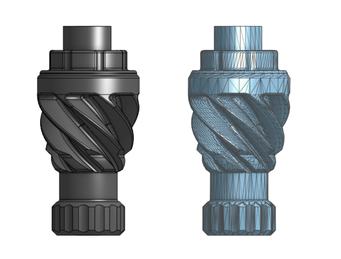
Solid formats (also called boundary representation, or B-rep) describe a part using exact mathematical geometry: precise surfaces, edges, and curves. A cylinder is stored as a true cylinder with a defined radius, not an approximation. STEP, IGES, and native CAD files are solid formats. Because the geometry is exact and editable, these formats are what CNC machining and any further CAD work require.
Mesh formats describe a part as a surface skin made of thousands of tiny triangles. A curved surface is approximated by many small flat facets rather than a true curve. STL, OBJ, and 3MF are mesh formats. They are ideal for 3D printing, where the part is built up in layers anyway, but they cannot be edited as parametric CAD and they lose the exact geometry of the original model.
What is a STEP File?
A STEP file (.step or .stp) is a solid CAD format used to exchange 3D models between different CAD programs and manufacturers. STEP stands for Standard for the Exchange of Product model data, and it is the industry's universal exchange format. A STEP file created in SolidWorks for example can be imported into Fusion 360, Onshape, or a machine shop's CAM software without losing its geometry.
Because STEP preserves exact, editable geometry, it is the preferred format for CNC machining and for any job where the part may need design changes. When a manufacturer asks for a CAD file to quote a machined part, STEP is almost always the right answer. It carries the true dimensions of the model, which is exactly what a CNC toolpath needs.
What is an STL File?
An STL file (.stl) is a mesh format that describes the surface of a part as a web of triangles. STL stands for stereolithography, the early 3D printing process it was created for, and it remains the standard file format for 3D printing.
The tradeoff with STL is resolution. Due to the surfaces being represented as triangles, it is by definition an approximation of the original model, a low-resolution STL shows visible faceting, while a high-resolution one captures smooth curves at the cost of a larger file. When exporting an STL, the resolution settings (often called chord height and angular deviation) determine how accurately the mesh represents the original model. For 3D printing, STL is the standard, and our guides to FDM and SLA printing cover how the file becomes a physical part.
An STL also carries no unit information. The file type stores only raw coordinate numbers, with nothing recording whether those numbers are millimeters or inches. A part modeled at 50 mm and the same part modeled at 50 inches produce STL files that look identical, and the software that opens it has to assume a unit. This is a common cause of parts arriving at the wrong scale, often off by a factor of 25.4 when millimeters and inches get swapped. A STEP file, by contrast, stores its units, which is one more reason it is the safer format when scale matters.
What STL is not good for is machining or editing. Because it holds no exact geometry, a machine shop cannot generate precise toolpaths from an STL the way it can from a STEP file.
What is an IGES File?
An IGES file (.igs or .iges) is an older neutral format for exchanging solid and surface geometry between CAD systems. IGES stands for Initial Graphics Exchange Specification, and for years it was the standard exchange format before STEP largely replaced it.
IGES still appears in some industries and older workflows, and it is particularly associated with complex surface data. For most modern manufacturing, though, STEP is the better choice: it handles solid models more reliably and is less prone to the small geometry errors that IGES translations can introduce. If you have the option to export either, STEP is usually preferable and more universal.
Native CAD Files
Native files are the proprietary formats of specific CAD programs: .sldprt for SolidWorks, .f3d for Fusion 360, .ipt for Inventor, and so on. They hold the full design, including feature history and parametric relationships, but they generally can only be opened in the original software they were generated in.
For that reason, native files are not ideal for sending to a manufacturer unless you know they run the same software. The safer practice is to export your model to STEP before sending it. You keep the native file for your own editing, and the STEP file gives the manufacturer a format they can open regardless of their CAD system. The exception is CAD or design work where the original feature history matters, in which case the native file may be needed.
If your question is whether to send a 3D model, a 2D drawing, or both, that is a separate decision covered in our guide to CAD files versus technical drawings.
How to Open and Convert CAD Files
You do not need expensive software to open most CAD files. Free viewers and several browser-based tools can open and inspect STEP and STL files, and most CAD programs, including free options like Fusion 360 for personal use, can open and export both. Autodesk maintains a helpful overview of common CAD file types if you want a deeper reference.
Converting between formats is where the solid-versus-mesh distinction matters. Exporting a STEP file to STL is straightforward: every CAD program does it, and you simply choose a resolution. Going the other way, from STL back to STEP, is far harder. Because the mesh holds no exact geometry, converting it into a clean, editable solid requires rebuilding the model, which is effectively reverse engineering rather than a simple file conversion. Plan your workflow around keeping a solid file whenever you can, so you are never stuck trying to recover one from a mesh.
Do you have an STL file that you need converted back to a STEP? We offer 3D scanning and reverse engineering services.
Common File Issues
Many quoting delays we see trace back to file problems rather than the part itself. The ones we see most often:
- Wrong units or scale. A model exported in the wrong units arrives at ten times or one-tenth its intended size. Confirming units before export prevents a part being quoted, or made, at the wrong scale.
- Low-resolution STL. An STL exported at coarse settings shows faceting that becomes visible on the printed part. Exporting at an appropriate resolution keeps curved surfaces smooth.
- Sending a mesh when a solid is needed. An STL sent for a CNC quote cannot be machined directly and will trigger a request for a STEP file, costing a round trip.
- Missing tolerances or specifications. A file shows geometry but not the critical dimensions, finishes, or material a part requires. Including that information, often as a drawing alongside the model, keeps the quote accurate.
Conclusion
The rules for choosing a format are short: solid formats like STEP carry exact geometry for machining and editing, mesh formats like STL are built for 3D printing, and converting from solid to mesh is easy while the reverse is not. When in doubt, a STEP file is the most versatile thing you can send, and an STL is the right call for printing.
To get your part quoted, upload an STL for an instant 3D printing quote, or send a STEP file for machining or CAD support. If your model needs work before it is production-ready, our CAD team can help.
Frequently Asked Questions
What is a STEP file?
A STEP file is a solid CAD format used to exchange 3D models between different CAD programs and manufacturers. It preserves exact, editable geometry, which makes it the preferred format for CNC machining and the most universal format to send when requesting a quote.
What is an STL file?
An STL file is a mesh format that describes a part's surface as a web of triangles. It is the standard file format for 3D printing. Because it approximates curves with flat facets and holds no exact geometry, it is not suitable for CNC machining or CAD editing.
STEP vs STL: which is better?
Neither is better overall; they serve different purposes. STEP is better for CNC machining and CAD work because it stores exact geometry. STL is better for 3D printing because it describes the surface mesh that printers build from. Send STEP for machining and STL for printing.
How do I open a STEP file?
STEP files can be opened with free CAD viewers, many browser-based tools, and most CAD programs, including free options like Fusion 360 for personal use. You do not need to purchase software simply to view or inspect a STEP file.
Can you convert an STL back to a STEP file?
Yes, but it is not a simple conversion. Because an STL holds no exact geometry, turning it into a clean, editable solid means rebuilding the model, which is effectively reverse engineering. Converting a STEP file to an STL, by contrast, is quick and routine.