Rapid Prototyping Guide: Methods, Materials, and Process Selection
Most product development failures trace back to problems that existed in the design long before manufacturing, but were only found after tooling was cut, assemblies were built, or a first article was rejected.
Rapid prototyping exists to compress that gap. With the advent of 3D printing, specifically producing CAD models as physical hardware quickly enough that teams can evaluate, adjust, and retest before tolerances, materials, and tooling decisions are locked in. The goal is to harshly evaluate current designs physically to help root out these problems early.
This guide covers the main rapid prototyping methods used in mechanical design development, how to match each to a specific validation goal, and what separates a prototype that yields real insight from one that wastes a build cycle.
What Is Rapid Prototyping in Manufacturing?
Rapid prototyping is a group of fabrication techniques that produce physical parts from 3D CAD data without the tooling investment or lead time of conventional production processes. It includes additive methods such as FDM, SLA, SLS, and MJF, as well as subtractive methods such as CNC machining, CNC Lathe, or Waterjet/Laser Cutting.
ISO/ASTM 52900 defines additive manufacturing as the process of joining materials to make parts from 3D model data, typically layer upon layer. Rapid prototyping draws from this set of processes and pairs them with subtractive techniques to cover a wider range of material and tolerance requirements than any single process can address alone.
The defining characteristic is speed relative to learning. A rapid prototype is built to answer a specific question about a design, assembly, or material before committing to more expensive or time-consuming manufacturing steps. When a prototype can be in hand within days of a design change, teams can run more cycles before committing, and more cycles typically mean fewer surprises downstream.
Rapid Prototyping vs. Production Manufacturing
A production part is built to a final specification. A rapid prototype is built to answer a specific question. That distinction drives every decision about process, material, and tolerance.
There are four prototype types commonly used in hardware development:
- Concept prototype. Evaluates aesthetics and spatial relationships before geometry is finalized. Used for early design decisions where form matters more than function.
- Fit prototype. Confirms assembly clearances, cable routes, mating conditions, and fastener access. Typically built before functional requirements are fully validated.
- Functional prototype. Carries a representative load, survives thermal exposure, holds pressure, or undergoes cycle testing at conditions close to the actual use case.
- Production-intent prototype. Uses comparable material class and tolerances to the final specification. Validates both geometry and process behavior together before scaling.
The mistake is using the wrong prototype type to make the wrong decision. A loose FDM print in PLA will not reliably validate a tolerance-critical press fit. A tight-tolerance machined aluminum part is unnecessary when the goal is ergonomic review. Matching prototype type to decision type is the first and most important step in keeping a prototyping program efficient.
Rapid Prototyping Methods and When to Use Each
The right process depends on what the prototype needs to demonstrate. Below is a breakdown of the four most common methods used in hardware development, with the tradeoffs that matter in real projects. For a deeper comparison of the additive processes specifically, see our guide to FDM, SLA, SLS, and MJF.
FDM: Fast Iteration and Early-Stage Builds
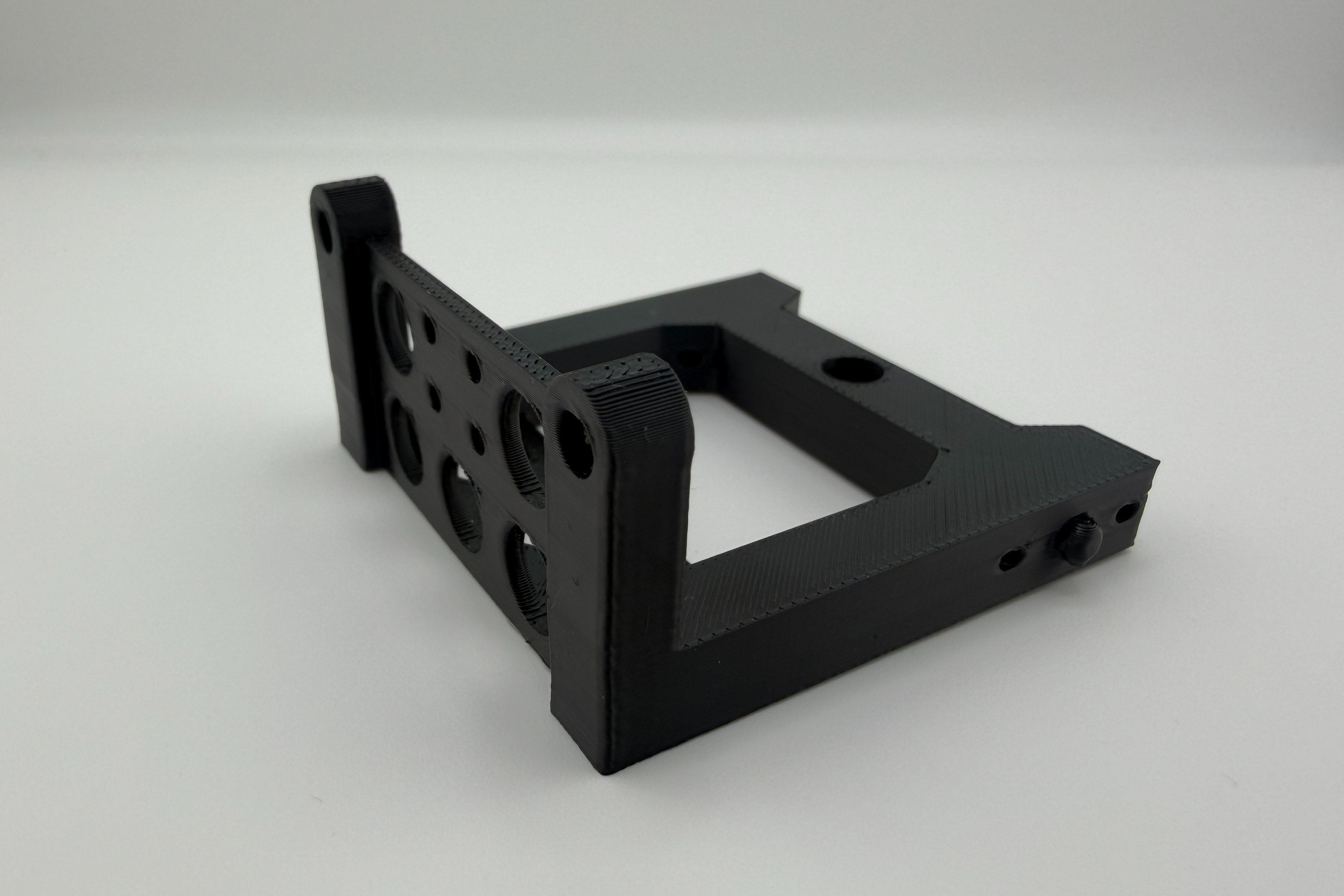
Fused deposition modeling extrudes thermoplastic filament layer by layer, making it the fastest and most cost-effective additive process for most early-stage prototype work. Parts are typically available within one to three business days. Per-part cost is low, and design changes carry no setup penalty, which makes FDM practical for running multiple variants in parallel.
FDM is well-suited for concept prototypes, fit checks, brackets, enclosures, and early functional builds where surface finish is not the primary evaluation criteria. Material options at Simple Machining include PLA and PLA-CF for general geometry and rigid structural checks, ABS and ASA for better temperature resistance and UV stability, and TPU 95A for flexible or impact-absorbing applications.
The tradeoffs matter for testing. Dimensional variation in FDM typically runs ±0.3 to 0.5 mm, depending on geometry, orientation, and feature size. That is acceptable for non-critical clearance checks and not acceptable for controlled fits or sealing interfaces. Interlayer bond strength runs roughly 50 to 80 percent of in-plane tensile strength, so parts loaded perpendicular to the build direction will behave differently than the material datasheet suggests. If the test involves directional load, build orientation needs to be part of the request.
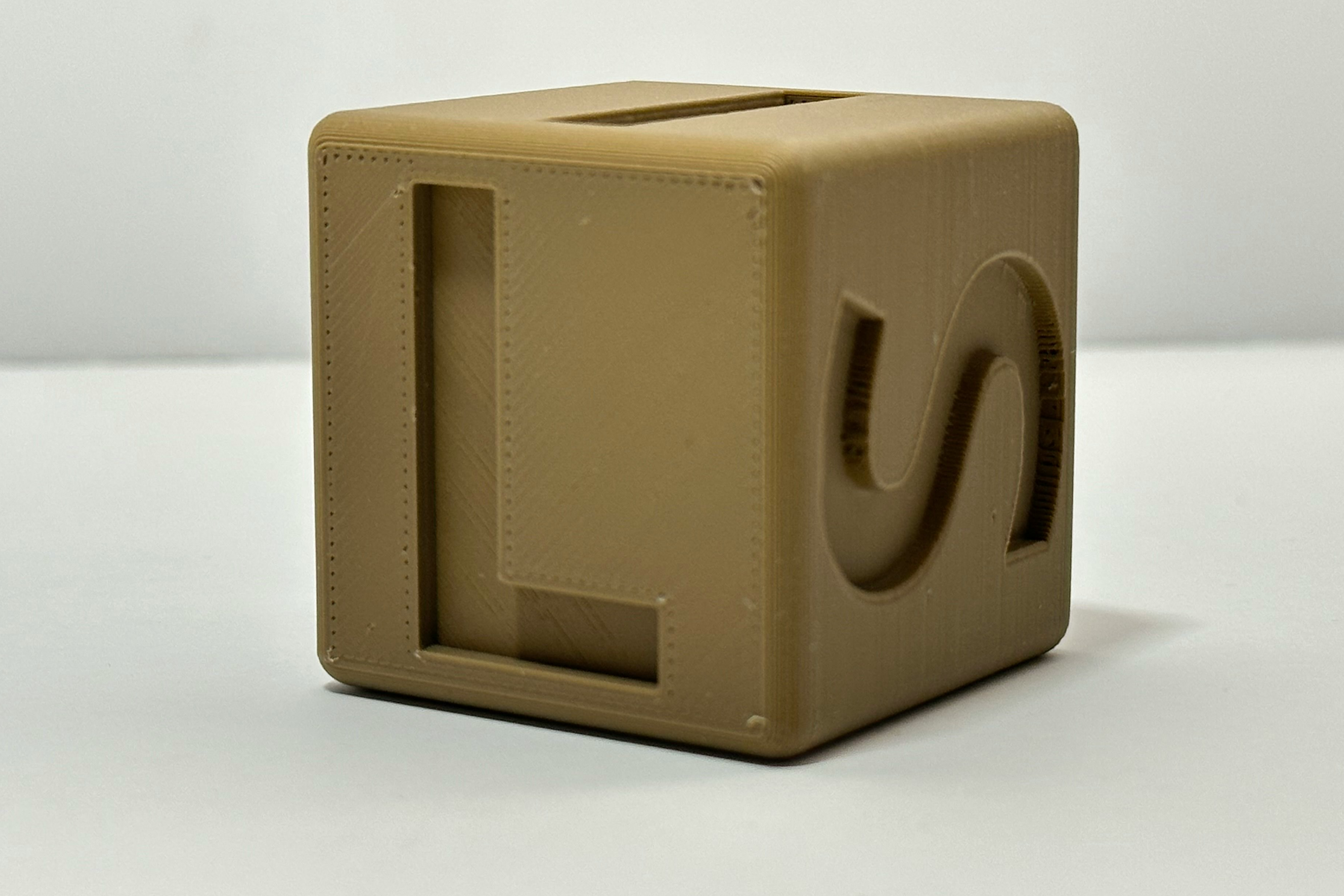
SLA: Surface Quality and Fine Feature Resolution
Stereolithography cures photopolymer resin with a UV laser, producing parts with smoother surfaces, finer feature resolution, and better dimensional consistency than FDM at equivalent layer heights. Lead times are similar, typically one to three days for most geometries.
SLA is the right process for appearance models, medical device housings, optical or fluidic components with small internal features, and any prototype where surface texture is part of what is being evaluated. SLA resins are generally more brittle than FDM thermoplastics and are not suited for functional testing under significant impact or cyclic load. Use SLA when the question is about form, surface quality, or fine geometry rather than structural performance.
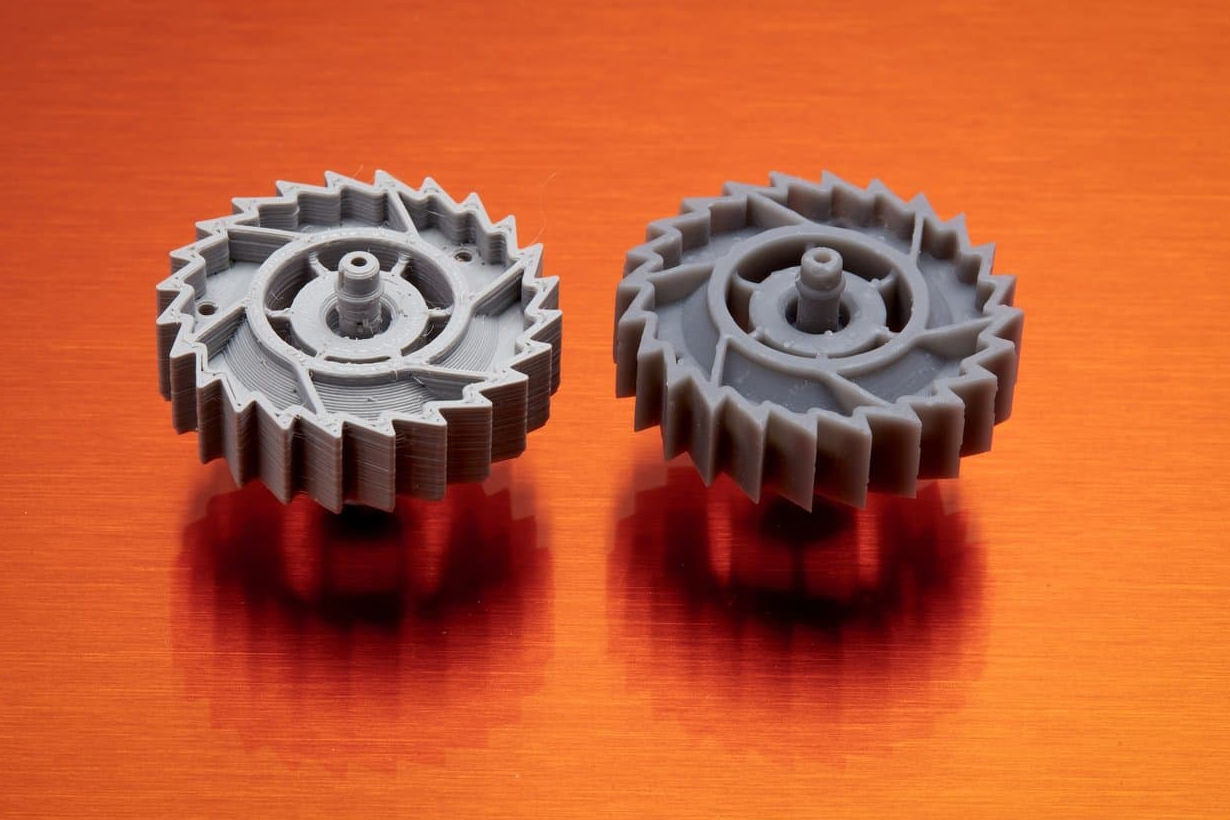
SLS and MJF: Functional Nylon Prototypes with Isotropic Properties
Selective laser sintering and Multi Jet Fusion both fuse nylon powder into parts without support structures, which allows complex internal geometries, thin-wall features, and assembled mechanisms that would be difficult or impossible to build in FDM. More importantly, the resulting parts have more isotropic mechanical properties than layer-deposited processes, which makes test results more representative of real loading conditions.
Nylon PA12, available in both SLS and MJF, offers tensile strength in the range of 45 to 50 MPa, good impact resistance, and reasonable chemical resistance. It is appropriate for brackets, enclosures, snap-fit assemblies, and functional components that will see actual handling or mechanical load. MJF typically produces tighter dimensional consistency and finer surface texture than SLS at comparable build parameters. Lead times are generally three to five business days.
When a functional prototype needs to behave closer to an end-use component without the cost or lead time of CNC machining, SLS and MJF are usually the right middle ground.
CNC Machining: Tolerance-Critical and Material-Specific Prototypes
CNC machining removes material from stock to produce parts with controlled dimensions, predictable surface finish, and access to engineering-grade metals and plastics that additive processes cannot replicate. For prototypes that need to behave like the final part, machining is often the only credible path.
CNC is the right choice when the prototype requires tight mating features or controlled fits (typically ±0.05 mm or better), clean sealing surfaces or O-ring groove geometry, threaded interfaces that will be cycled under load, or specific metal behavior such as stiffness, conductivity, corrosion resistance, or weldability. Common prototype materials include aluminum 6061-T6 for structural and thermal applications, stainless 303 or 304 when corrosion resistance or sterilizability matter, and Delrin or PEEK when a stiff, machinable plastic is preferable to metal.
The tradeoffs versus additive are cost and lead time. A machined prototype typically runs five to ten business days and costs more per part than an equivalent 3D-printed geometry. For most teams, the right approach is to use additive methods for early iteration and reserve machining for production-intent builds where the test data needs to be defensible. Tolerancing decisions also have a direct impact on machining cost and lead time, so calling out only the features that truly matter keeps the prototype program efficient.
Simple Machining's CNC milling service supports prototypes and low-volume production, with large-format capability up to 72" x 48" x 24" and finishing options including anodizing, powder coating, and electroplating.
How to Choose the Right Rapid Prototyping Method
Start with the question the prototype must answer, not the process.
Define the validation target first. Is this a form and aesthetics review, a fit and assembly check, a functional test under load or temperature, or a production-readiness build? Each requires a different level of dimensional accuracy and material fidelity. A prototype that tries to answer all of these at once usually answers none of them reliably and costs more than necessary.
Identify what cannot be wrong. On most parts, only a handful of features are truly critical: a bore diameter, a sealing face, a load-bearing wall. Everything else can be treated as reference geometry. A good prototype request calls those features out explicitly with tolerances attached. That allows the fabrication partner to optimize the setup for the features that matter, rather than treating the entire part as equally important.
Then match process to requirements:
- Complex geometry, frequent changes, and non-critical tolerances: start with FDM.
- Fine features or surface quality as the primary evaluation criteria: SLA.
- Functional nylon prototype with isotropic properties needed: SLS or MJF.
- Controlled fits, metal behavior, or production-intent testing: CNC machining.
If the geometry needs review before a process is selected, Simple Machining's CAD drafting service includes DFM assessment, which can identify features likely to cause fabrication problems before the first order is placed.
The Real Cost of Rapid Prototyping
A single 3D-printed or machined prototype will always cost more per unit than the same part produced at volume through injection molding or high-volume CNC. That comparison misses the point. The relevant cost is not the cost of building the prototype. It is what the prototype prevents you from spending later.
Tooling changes after mold steel is cut routinely run $5,000 to $25,000 per revision, depending on complexity. A failed first-article inspection during a production run can delay a program by weeks and require a full re-quote from the supplier. Scrapped inventory from a tolerance or fitment problem discovered after a batch ships is even more expensive, and that cost compounds when it reaches a customer. Every one of these failures traces back to a question that could have been answered with a $200 to $2,000 prototype built weeks earlier in the timeline.
The math works when you consider what a typical prototype cycle actually prevents:
- A concept prototype at $50 to $300 replaces a tooling revision that would cost 10x to 100x more once geometry is locked.
- A fit prototype at $100 to $500 catches assembly interference before production fixtures are designed around bad assumptions.
- A functional prototype at $200 to $2,000 validates load paths, thermal behavior, or seal performance before committing to a material and process that may not survive qualification testing.
- A production-intent build at $500 to $5,000 confirms that the final geometry, material, and tolerances produce a part that meets specification, before a production order is placed.
At each stage, the prototype cost is a fraction of the cost it displaces. Teams that skip prototyping do not save money. They defer risk into a phase where the cost of being wrong is orders of magnitude higher.
There is also a less visible cost: time. A design change during prototyping takes days. The same change after tooling takes weeks, and after product launch, it may take months. For startups operating on venture timelines or contract manufacturers facing hard delivery dates, the schedule compression that prototyping provides is often worth more than the direct dollar savings.
The goal is not to prototype everything. It is to prototype the decisions that carry the most risk. A part with well-understood geometry, a proven material, and non-critical tolerances may not need a physical build. A part with a new snap-fit geometry, a first-time material selection, or a sealing interface that has never been tested should never go to production tooling without at least one physical validation cycle.
Where Rapid Prototyping Has the Most Impact by Industry
Physical hardware exposes problems that CAD review and simulation do not. The industries below use rapid prototyping differently, but the underlying value is the same: catching design problems while changes are still cheap.
Medical Devices
Device housings, ergonomic handles, and assembly interfaces are commonly validated with rapid prototypes before production tooling is committed. Even when the prototype is not built in the final production process, it needs to be consistent enough to support documented testing. Repeatability matters at the prototype stage in medical development because test results need to be defensible as the design progresses toward regulatory review.
Robotics and Automation
Sensor mounts, actuator brackets, and cable management features change frequently during robot development as motion envelopes and component selections evolve. FDM handles most of this early iteration efficiently. When a structural bracket moves into a load-bearing role or a housing needs tight tolerances, machined parts take over. The value of prototyping in robotics is often less about any single part and more about testing the assembled system. Assembly problems are almost always cheaper to find with a physical build than with a finished machine.
Aerospace and Defense
Rapid prototyping in aerospace is primarily used for development fixtures, duct mockups, and housings for non-flight hardware. Lead time advantages are real on programs where schedules are tight, but documentation and material traceability requirements mean the prototype request needs to be as well-structured as a production order.
Startups and Early-Stage Hardware Teams
This is where rapid prototyping has the most leverage relative to capital available. A startup that can produce credible functional prototypes before a Series A has a fundamentally different conversation with investors, customers, and contract manufacturers than one presenting only CAD renderings. On-demand manufacturing with no MOQ makes that possible without committing capital to tooling or minimum run quantities.
Need functional prototypes fast? Get an instant quote through Simple Machining's auto-quoter, or submit files for a manual quote on SLA, SLS, MJF, or CNC parts.
What to Include in a Rapid Prototype Request
Include the following in every request:
- CAD file and revision number. STEP format preferred for CNC; STL or 3MF accepted for 3D printing. If both a 3D model and a 2D drawing exist, submit both to avoid ambiguity.
- Purpose of the prototype and the specific question it needs to answer.
- Critical dimensions with acceptable variation called out explicitly.
- Material and process preference, or the functional requirement if the process is open.
- Quantity, lead time requirement, and any post-processing needs such as tapped holes, surface finish, or hardware insertion.
If the failure mode the prototype is meant to test is already known, include it. A fabrication partner who understands what is being tested is better positioned to flag process or geometry decisions that could compromise the result before the part is built.
| See how we can provide parts in as quick as 1 business day
Conclusion
Rapid prototyping reduces the cost of being wrong during product development. The process works when the prototype is matched to the question it needs to answer: the right method, the right material, and the right tolerance requirements for the stage of development.
If you need help selecting a process, evaluating geometry, or planning a prototype program, Simple Machining can review your application and recommend an approach that fits your timeline and validation goals. Start a quote or contact us directly.
FAQ
What is rapid prototyping in manufacturing?
Rapid prototyping refers to fabrication methods that convert CAD data into physical parts quickly, without production tooling, so teams can evaluate form, fit, or function during development. Common processes include FDM, SLA, SLS, MJF, and CNC machining. The right process depends on what the prototype needs to demonstrate.
Is 3D printing always the best rapid prototyping method?
Not always. 3D printing is usually the fastest and most cost-effective option for complex geometry and frequent design changes. CNC machining is the better choice when controlled tolerances, specific engineering materials, or metal properties are required to produce test results that are representative of the final part.
When does it make sense to use CNC machining for a prototype instead of 3D printing?
Use CNC machining when the prototype needs controlled fits, clean sealing surfaces, threaded interfaces, or needs to behave like a final metal or engineering plastic part. Machining is also preferable when the test involves mechanical load, thermal cycling, or pressure that additive parts may not replicate reliably.
How many prototype iterations should a hardware program plan for?
Most programs benefit from at least two to three distinct builds: an early fit prototype to check assembly and clearances, a functional prototype to validate load paths and critical interfaces, and a production-intent build to confirm geometry and process behavior before scaling. Programs that skip early-stage builds tend to find the same problems later at higher cost.
What is the most important input in a rapid prototype request?
A clear statement of what the prototype must prove and which features cannot be wrong. Critical dimensions, interface requirements, material expectations, and the test condition driving the build all help the fabrication partner select the right process and avoid a second run.
Disclaimer
The content appearing on this webpage is for informational purposes only. Simple Machining makes no representation or warranty of any kind, be it expressed or implied, as to the accuracy, completeness, or validity of the information. Any performance parameters, geometric tolerances, specific design features, quality and types of materials, or processes should not be inferred to represent what will be delivered by Simple Machining. Buyers seeking quotes for parts are responsible for defining the specific requirements for those parts. Please refer to our terms and conditions for more information.