Understanding Rectilinear vs Grid Infill for 3D Printing
Introduction
Infill selection is a key part of ensuring prints meet requirements in their application. Infill influences stiffness and strength, support under top surfaces, print time, and, in some cases, dimensional stability. It is important to understand the application and practical print constraints when deciding which infill geometry to use.
This article focuses specifically on rectilinear vs grid infill. Both are common 2D patterns, but they behave differently because grid creates line intersections within the same layer and rectilinear typically does not.
For a more general comparison, read our guide: Understanding 3D Printing Infill for Better Part Design.
In This Guide You Will Learn:
• What actually changes when switching between rectilinear vs grid infill
• When grid infill 3d printing settings can improve strength, and when they do not
• Why grid intersections can cause noise, scarring, or failed prints
• How to choose based on failure mode
Rectilinear vs Grid Infill: The Basic Differences
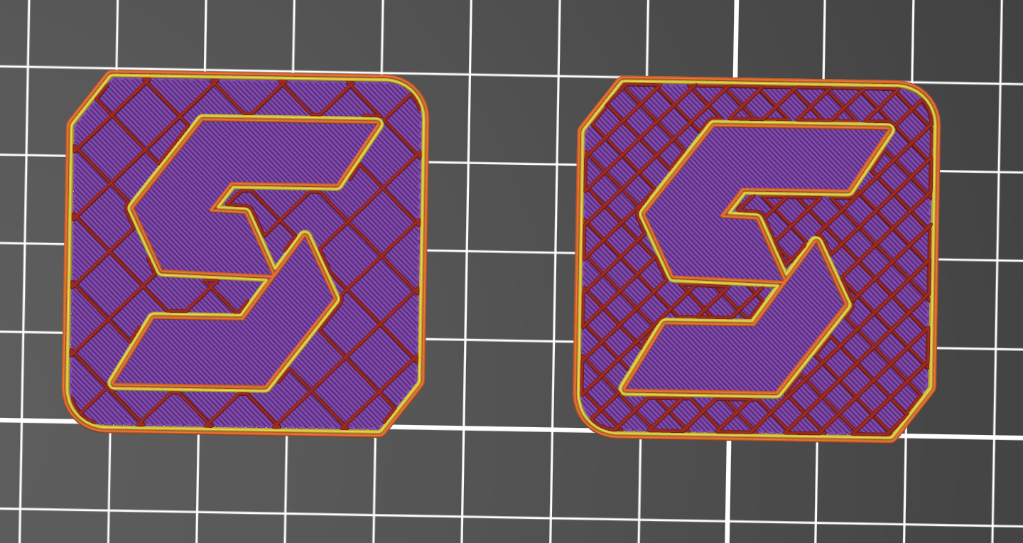
Rectilinear infill
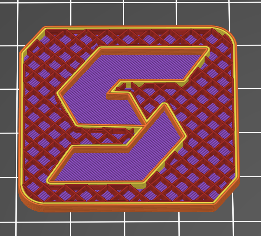
Rectilinear FDM Infill
Rectilinear infill prints straight, parallel lines within a layer, then rotates the line direction on the next layer, commonly by 90 degrees. Crossings occur between layers rather than within the same layer, so the tool head is at a higher speed, for longer.
In practical terms, rectilinear builds a predictable lattice through the Z axis, because it avoids same-layer intersections, and it is generally more tolerant of small process errors such as slightly high flow or elevated temperature.
Rectilinear is also a strong starting point when top surface quality is a priority. The alternating layers distribute support under the top surface layers more evenly, which can help reduce pillowing on broad roofs when paired with adequate top layers.
Grid infill
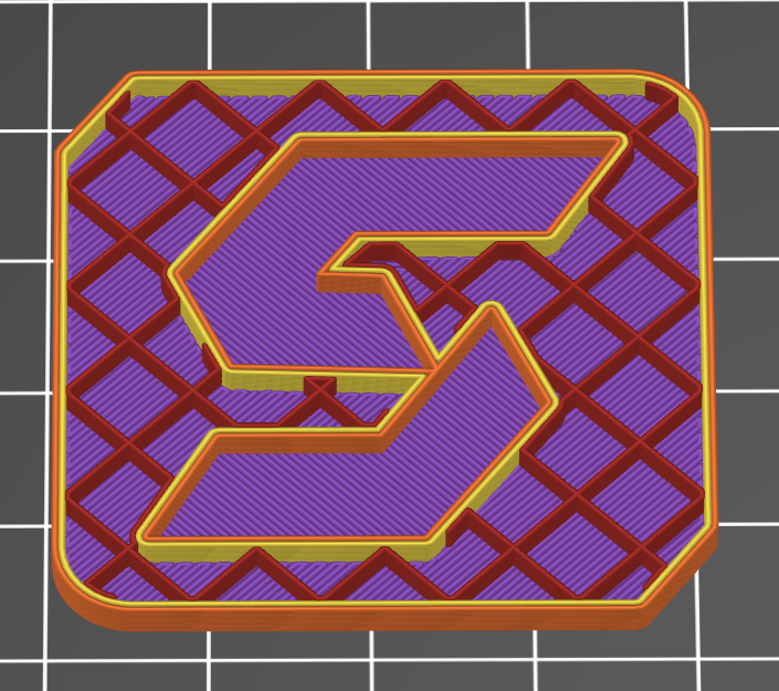
Grid FDM Infill
Grid infill prints two perpendicular line sets in the same layer. The lines intersect at repeating points across the layer, so each layer contains many crossings where material is deposited over a line printed moments earlier.
The advantage is that each layer has structure in two directions, which can increase in-layer stiffness for some geometries at the same infill percentage. The tradeoff is that every intersection is a local accumulation point. If the flow is slightly high, the polymer is still very soft, or the printer is running fast with aggressive acceleration, crossings can build into raised sections.
Raised sections increase the chance of nozzle contact, internal scarring, and, on long builds, occasional layer shifts on some machines. Grid tends to perform best when flow, temperature, cooling, and infill speed are well controlled.
What Infill directly does and doesn't affect
What infill controls
Support under top surfaces
Infill acts like scaffolding under the top solid layers. If a part has a broad roof area, the spacing and consistency of infill beneath the skin can influence pillowing, surface texture, and the number of top layers required.
Core stiffness in specific directions
At a given wall thickness, infill can change how much a part deflects, especially in bending, where the shell is thin, and the core is doing more of the work. Pattern choice matters most when the part’s load path is sensitive to in-plane stiffness.
Print time and risk
Higher infill percentages increase print time and material use. Pattern choice can also change risk. For example, patterns such as a grid with frequent same-layer intersections can be more sensitive to slightly high flow or aggressive motion settings.
Local compression resistance
Infill can matter for features that see localized squeezing or clamping loads, especially where the shell is thin, and the load is transferred into the core.
What infill usually does not control
Layer-to-layer strength
If a part is failing along layer lines, the infill pattern is rarely the primary fix. Orientation, temperature, cooling, and wall strategy typically matter more.
Stress concentrations
Cracks that start at sharp internal corners, holes, or thin transitions are primarily failures due to the geometry. Infill changes the internal structure, but it does not remove a stress riser.
Dimensional accuracy by itself
Dimensional errors are more often driven by calibration, shrinkage, warping, and machine dynamics than by whether the core is grid or rectilinear.
Is grid infill stronger than rectilinear?
Sometimes. But the honest answer is that published results vary because the test setup matters. Infill pattern performance depends on infill density, wall strategy, raster direction relative to load, polymer, nozzle size, layer height, and print temperature.
What published testing suggests
A 2025 peer-reviewed study published in the “National Library of Medicine” on PLA test pieces reported higher ultimate tensile strength for grid than rectilinear under their specific conditions. In that configuration, the grid averaged 21.91 MPa while the rectilinear averaged 16.65 MPa at 60% infill with three walls and 0.2 mm layers. The result suggests that the grid is significantly stronger than the rectilinear grid.
A separate 2025 paper, however, reported grid and line-style infill showing essentially identical tensile strengths in their test setup (19.40 MPa vs 19.47 MPa). This is a useful reminder that the same pattern names can behave differently depending on slicer implementation and parameter choices.
When deciding on an infill type for your part, it is more important to consider the application than pure lab results.
Top surface support and finish
If the main problem is top surface quality, rectilinear is usually the way to go. Prusa’s infill documentation notes that rectilinear can provide double the support for top layers compared to grid, using the same amount of material. This matters when a part has a broad “roof” area that is closing over sparse infill.
Grid can still support top layers well, but the crossing nodes can create localized height variation that shows up as texture changes or inconsistent skin lines.
Why support under top skins is not just about infill percentage
Two prints can both be 15% infill and still behave differently under top skins. The difference is the spacing between support points and how evenly those points are distributed under the skin.
Rectilinear can create a more uniform support map across layers because it builds a lattice in Z without stacking crossings within a single layer.
Print Time and Risk
Grid-related issues are often visible early in a print. A ticking sound during infill can indicate the nozzle is riding over raised intersections, and scuff marks inside the part can be a sign of nozzle contact. On long builds, repeated impacts can increase the chance of a layer shift on some machines, while rectilinear tends to be more predictable because it reduces same-layer crossings and uses longer, more continuous toolpaths.
How to choose between rectilinear and grid
The right choice depends on the requirement you are trying to optimize for. Pattern selection should be driven by the failure mode, not by default profiles.
Choose rectilinear when the main risk is print failure or top surface quality Rectilinear is usually the better starting point when repeatability is the priority. Common situations where rectilinear is a better fit:
• Long prints where a single failure is costly
• Large parts with broad flat top surfaces
• Printers that show nozzle contact or “ticking” with grid-style crossings
• Profiles that run high acceleration or higher infill speeds
• Parts where internal scuffing could telegraph to exterior walls
Choose grid when you need more in-layer structure Grid can be useful when the part benefits from more structure within each layer, and when the printer can run intersections cleanly. Common situations where grid is a better fit:
• Parts where in-plane stiffness is the limiting factor at a given infill percentage
• Shorter builds where you can validate the behavior quickly
• Geometries where minor internal scarring is acceptable
• Profiles that are well-tuned for flow, temperature, and cooling
• Builds where the infill is not printing under aggressive speed settings
A simple rule of thumb
• If the primary risk is print failure, start with rectilinear.
• If the primary requirement is a stiffer internal core and intersections run cleanly, test grid.
Common print issues with grid infill
Grid infill problems are often blamed on the pattern, but the root cause is usually process control. Intersections amplify small issues in flow, temperature, and motion.
Common causes of intersection buildup:
• over-extrusion
• Excessive nozzle temperature for the filament
• Insufficient part cooling on infill
• Infill speed that is too high for the machine’s pressure control
• Aggressive acceleration and jerk settings that increase vibration at short segments
At Simple Machining, we have worked hard to optimize our print profiles to ensure the best quality prints are delivered to customers. You can start your quote and get an order within days, reducing headaches in dealing with the nitty-gritty.
When to consider other infill geometry
Line-based patterns are not always the best option for multi-directional loads. If a part sees torsion, bending in multiple axes, or impact, a 3D infill pattern can sometimes deliver more uniform behavior. The correct approach is still the same. Define the failure mode, choose a candidate, and validate.
Conclusion
Grid can produce a more solid interior and may increase measured strength in some configurations. It also adds intersection risk that can reduce repeatability.
Rectilinear is often the reliability-first baseline. It avoids same-layer crossings, supports top skins efficiently, and tends to run cleaner on a wide range of machines.
FAQ
Is grid infill stronger than rectilinear?
Grids can perform better in some configurations because each layer contains structure in two directions. Published results vary, and some setups show little difference. Strength depends on density, wall strategy, polymer, and load direction.
Why can grid infill cause noise or scarring during a print?
Grid creates many same-layer intersections. If those crossings build up into raised nodes, the nozzle can contact them, leading to ticking sounds, internal scuffing, and, in long prints, occasional layer shifts on some machines.
When is rectilinear a better choice vs grid infill?
Rectilinear is a strong baseline when repeatability and top surface quality matter. It typically runs cleaner because it avoids same-layer intersections and uses longer, more continuous strokes.
How do rectilinear and grid change part stiffness at the same infill percentage?
At the same infill percentage, a grid can produce a stiffer “feel” in the plane of the layers because each layer contains structure in two directions. Rectilinear alternates directions between layers, which can make stiffness more dependent on load direction and wall thickness. In both cases, perimeters and part geometry usually dominate overall stiffness, so validate with a quick deflection test if stiffness is the requirement.
Which pattern is better for supporting inserts, screws, or compression features?
For fasteners and localized compression, the most important factor is how much solid material exists around the feature. Perimeters, solid top and bottom regions, and dedicated bosses typically matter more than whether the core is grid or rectilinear. If a feature is transferring load into the core, the grid can provide more uniform support under compression in some geometries, but for critical hardware, it is best practice to design and slice the region as solid.
The Simple Machining Team
The Simple Machining Team supports engineers and product teams with on-demand manufacturing, including production-intent 3D printing, CNC machining, and DFM guidance to reduce risk and improve part performance.
Disclaimer
The content appearing on this webpage is for informational purposes only. Simple Machining makes no representation or warranty of any kind, be it expressed or implied, as to the accuracy, completeness, or validity of the information. Any performance parameters, geometric tolerances, specific design features, quality and types of materials, or processes should not be inferred to represent what will be delivered by Simple Machining. Buyers seeking quotes for parts are responsible for defining the specific requirements for those parts. Please refer to our terms and conditions for more information.