The Difference Between CAD Files and Technical Drawings
CAD files are 3D digital models of a part, used to define its shape, dimensions, and features for manufacturing. They are created in software like SolidWorks, Fusion 360, or Autodesk Inventor, and saved in formats such as STEP, STL, or IGES.
For engineers and buyers requesting machined or 3D-printed parts, one of the most common sources of quoting delays is confusion over file submissions, specifically whether to upload a CAD file, a technical drawing, or both. Understanding the role each file plays in the quoting and manufacturing process can save time and prevent costly miscommunications.
This post breaks down the differences between CAD files and technical drawings, why both may be required, and how to avoid common mistakes when submitting parts for on-demand manufacturing.
What Are CAD Files?
CAD stands for Computer-Aided Design. A CAD file is the digital container for a part's geometry, the file a designer creates and a manufacturer uses to understand what to build.
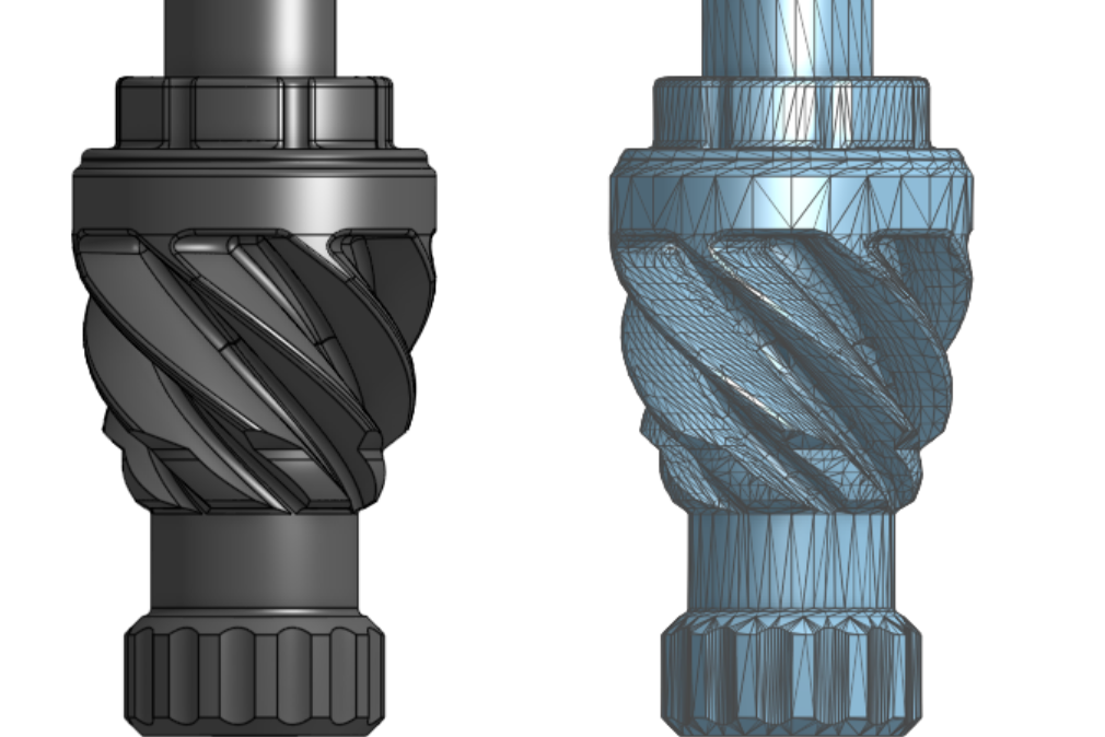
In modern manufacturing workflows, CAD files almost always refer to 3D models. They store the part's shape, internal features, fillets, holes, threads, and any geometry needed to recreate the part physically. The file is created in a CAD program, where the designer builds the part feature by feature, and saved either in the program's native format or exported to a neutral format that other software can read.
CAD files do not always carry every piece of information a manufacturer needs. They define geometry, but they typically do not specify materials, surface finish, tolerances tighter than nominal, or inspection priorities. That is where technical drawings come in, and why both files are often submitted together.
For projects where geometry alone is enough, most 3D printing work, prototype CNC parts at standard tolerances, or simple turned components, a clean STEP file is sufficient to quote and produce a part. For tighter-tolerance or production CNC work, a CAD file paired with a technical drawing is the safer submission. Teams without an in-house designer can have files created or cleaned up by a CAD drafting service before sending them to manufacturing.
Common CAD File Types: STEP, STL, IGES, and More
Not all CAD files are created equal. Each format encodes geometry differently, and the right choice depends on what the file will be used for.
STEP (.step or .stp) is the standard for 3D data exchange between CAD systems. It preserves exact, mathematically defined geometry, which is what CNC machinists and CAM software need to generate accurate toolpaths. Simple Machining requires STEP files for all CNC quoting.
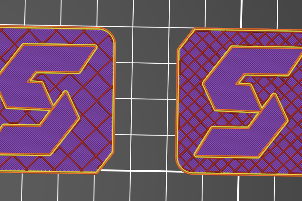
STL (.stl) stores geometry as a mesh of triangles approximating the surface of the part. Fine for 3D printing, where the printer slices a mesh anyway. Not suitable for CNC machining, since the triangulated surface introduces faceting that compromises tight tolerances and clean curves.
IGES (.iges or .igs) is an older neutral format that predates STEP. It is still readable by most CAM software but is more prone to translation errors, missing surfaces, and gaps that require cleanup before machining. Use STEP if you have the option.
Native formats (.sldprt, .ipt, .prt, .f3d) are the proprietary formats of CAD software like SolidWorks, Inventor, Creo, and Fusion 360. They preserve full design history, parametric features, and editing capability. Send these only when the manufacturer specifically supports your CAD program. Otherwise, export to STEP for portability.
DWG and DXF are 2D formats, primarily used for technical drawings and flat-stock work like laser cutting or sheet metal nesting. They are not appropriate for 3D part submission.
For most engineers submitting parts for manufacturing, the rule is simple: STEP for CNC, STL for 3D printing, native files only when explicitly requested.
Need help preparing CAD files for manufacturing? Our CAD team handles geometry, technical drawings, and DFM in one workflow, so your files arrive at the manufacturer ready to quote.
What Is a Technical Drawing?
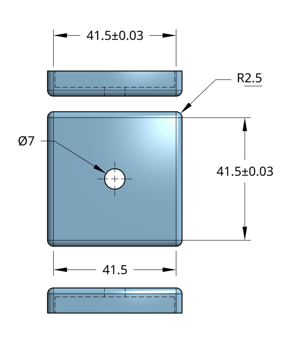
A technical drawing (or engineering drawing) is a 2D document, typically in PDF format, that defines additional specifications not always present in the CAD model. It supports manufacturing by controlling how the part should be machined and inspected.
Tolerances
Tolerances specify acceptable dimensional variation. For example, a hole specified at Ø10.00 mm ±0.05 mm means the diameter can vary from 9.95 mm to 10.05 mm. These are critical in assemblies where precise fits are required.
Surface Finishes
Surface finish requirements define roughness or smoothness using parameters like Ra (arithmetic average roughness). For instance, Ra 1.6 µm is typical for machined surfaces, while Ra 0.8 µm might be required for sealing interfaces.
Thread Callouts
Drawings identify thread types (e.g., M6 × 1.0 or ¼”-20 UNC), depth, and class of fit. This eliminates ambiguity in hole features that may appear as plain bores in CAD files.
Hole Depths
Drawings specify whether holes are through, blind, or counterbored, and include callouts for depth tolerances, avoiding misinterpretation from 3D geometry alone.
Critical Dimensions
These are dimensions that directly affect function or assembly. They are often flagged with symbols (e.g., a triangle or box) to alert machinists to their importance.
Material Notes
Drawings list required materials (e.g., 6061-T6 aluminum, 316 stainless steel), and may include specifications for hardness, grain direction, or certification needs.
Datum References
Datums anchor measurement systems during inspection. They define starting points for GD&T features such as flatness, perpendicularity, and true position.
Why You Need Both for Accurate Machining Quotes
The CAD file communicates geometry and enables toolpath generation. The technical drawing provides critical detail for:
- Fit and function (via tolerances and dimensions)
- Manufacturing requirements (threads, finishes)
- Inspection and quality assurance (datums and notes)
Without both, assumptions can lead to delays, incorrect features, or quote revisions. Simple Machining often requests both files to provide accurate, dependable pricing.
Common Quoting Errors Due to File Submission
Here are typical mistakes that disrupt the quoting workflow:
- Submitting only a screenshot or photo of the part
- Uploading a PDF drawing without an accompanying 3D model
- Sending an STL file for CNC jobs (intended for 3D printing only)
- Omitting threads, tolerances, or revisions in the drawing
Each of these adds unnecessary time and confusion.
Best Practices for Submitting Manufacturing Files
Always Provide a STEP File for CNC Jobs
STEP files are the industry standard for 3D data exchange. They maintain precise geometry and are readable by most CAM systems. STL files, which only include triangulated surfaces, are not suitable for machining.
Include a PDF Technical Drawing for Features Requiring Control
If your part has any functional geometry or surface specification, a 2D drawing is essential to define intent beyond what is visible in 3D.
Match Revision Numbers Between Files
Inconsistent revisions between CAD and drawings cause errors in quoting and production. Always update both files to reflect the same revision level.
Use the Drawing to Define Critical Features
Don’t rely on embedded dimensions in the CAD file or screenshots. The drawing should explicitly control tolerances, threads, and surface finishes.
Review Files for Accuracy Before Uploading
Ensure all data is visible, dimensioned correctly, and consistent across files. Small errors can delay quoting by days.
Need Help Preparing Files?
Our team can assist with CAD file formatting, drawing standards, and best practices for quoting. We’re here to help ensure your parts are ready for production. We generate reference drawings FOR FREE with every CAD project & can generate full technical drawings for a flat fee per part. Learn more about our technical drawing services here
Conclusion
CAD files and technical drawings each play an essential role in the on-demand manufacturing workflow. CAD files define the shape; technical drawings define the intent. Submitting both gives your machining partner the context needed to quote quickly and produce accurately.
Not sure what to submit? Reach out to our team to ensure your files are manufacturing-ready.
Disclaimer
The content appearing on this webpage is for informational purposes only. Simple Machining makes no representation or warranty of any kind, be it expressed or implied, as to the accuracy, completeness, or validity of the information. Any performance parameters, geometric tolerances, specific design features, quality and types of materials, or processes should not be inferred to represent what will be delivered by Simple Machining. Buyers seeking quotes for parts are responsible for defining the specific requirements for those parts. Please refer to our terms and conditions for more information.