Designing Threads for SLS PA12: Pitch, Engagement, Reliefs, and Finishing
Printed threads in SLS PA12 offer a fast and cost-effective way to produce functional prototypes without post-machining or tapping. However, not every design will succeed in the first try. Understanding how nylon powder behaves during sintering, and how print orientation and finishing affect geometry, is key to deciding when printed threads are practical.
In this article, you will learn:
- How printed threads perform in SLS PA12 compared to tapped threads.
- Which thread sizes, geometries, and orientations are most reliable when printed.
- How to design thread geometry for printability and fit.
- Simple inspection steps to confirm functional threads before assembly.
Learn more about Selective Laser Sintering in our overview here
What Makes Printed Threads Viable in SLS PA12?
SLS PA12 can produce durable threads for low-torque, coarse-pitch fasteners when designed correctly. The fused-powder process can resolve features down to about 0.3 mm, but resolution decreases with curvature, overhangs, and orientation. For this reason, coarse threads, typically M8 or 1/4-20 and larger, deliver the most reliable results. Smaller threads often fuse between flanks or lose definition during bead blasting and post-processing.
Printed threads are most effective when speed and simplicity matter more than tight dimensional accuracy. They eliminate the need for tapping, reduce tooling costs, and allow housings, caps, or fixtures to be produced in a single build.
SLS Thread Design Rules for Nylon 12
Designing threads directly in SLS PA12 requires balancing detail resolution, powder flow, and thermal behavior. The following guidelines turn that balance into repeatable, functional geometry without post-machining.
1. Choose the right pitch and thread form
As SLS typically prints in 110µm-80µm layers (effectively resolution), fine pitches (<1.25 mm) often fuse between flanks because the laser spot overlaps between peaks. Coarse threads such as M8×1.25 or larger, print more consistently and allow better powder removal. Use standard metric coarse or UNC profiles for the most reliable performance, and avoid custom fine threads unless you plan to re-tap later.
If possible, slightly modify the thread form by flattening the crests and roots by 0.05–0.1 mm. This truncated profile reduces stress concentration and compensates for a minor sintering bulge at the flanks.
2. Keep Engagement short and strong
Threads deeper than about three times the pitch rarely add meaningful strength in SLS PA12 because the nylon reaches its shear limit before extra turns engage effectively. Deeper threads also trap heat and can distort during cooling. Target an engagement of 2–3× the nominal pitch. If you need more capacity, increase the thread diameter or use a metal insert instead of adding depth. For background on why strength gain plateaus with depth (ineffective thread length ≈ 2P for through holes and ≈ 3P for blind holes), see Ptiček et al. (2022) on ineffective thread length.
3. Design for clean starts and stress relief
Add a 45° lead‑in chamfer 0.5-1x the pitch. This chamfer helps the screw self‑locate and minimizes cross‑threading on rough surfaces. Include a run‑out groove or relief pocket at the end of blind holes so the fastener seats fully without bottoming out. Rounded roots and crests distribute load and reduce crack initiation, especially under torque.
4. Reinforce the surrounding boss or wall
Treat every thread as a loaded feature, not a decorative one. Maintain wall thickness at least 1.5× the nominal thread diameter and 3× the layer height, whichever is greater. At Simple Machining, our SLS Printing Service uses 110µm layer heights, so we recommend a wall thickness of at least 330µm. Add a radius transition (≥0.5 mm) between the boss and adjacent surfaces to minimize warping. If the part has multiple threaded holes, space them at least two diameters apart to prevent thermal stress overlap during printing.
5. Allow for post‑processing impact
Bead blasting, dyeing, and heat exposure can change thread dimensions from nominal. Plan your clearances to absorb that variation. If the threads are functional, request minimal blast pressure or masking of thread zones during finishing.
6. CAD modeling tips for additive threads
Use helical cut features rather than surface sweeps to maintain a clean, parametric profile. Check that the thread start and end align with the build axis. Add a small core hole beyond the thread end to allow trapped powder removal. For large internal threads, include powder escape slots near the root to prevent compaction.
Need assistance adding threads to your SLS design? Our design team can provide DFM services and optimize your design for SLS.
SLS Thread Orientation and Surface Finish Effects
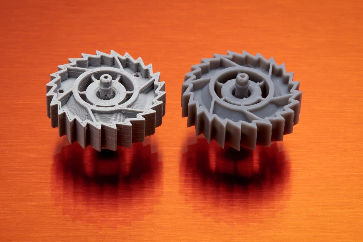
Thread orientation directly affects pitch accuracy and circularity. Vertically printed threads maintain better roundness but tend to have rougher flanks due to the layer-by-layer build texture. Horizontally printed threads, in contrast, produce smoother flanks but slightly elliptical pitch diameters caused by layer stepping and support geometry. For critical components, it's essential to design with this compromise in mind. Additionally, if the project budget and timeline allow, print test samples in both orientations during your first build to compare fit and surface quality.
Thread Fit and Inspection After Printing
Printed threads rarely meet ISO 6H or 6g tolerance classes without machining. A quick functional test confirms whether printed threads are ready for use or need light cleanup before use.
When to Print Threads vs. When to Tap or use inserts
A simple rule of thumb applies when choosing between printed and tapped threads:
- Print threads when they are large, coarse, low-torque, and short in engagement length.
- Tap threads when they are small, fine-pitch, high-load, or used in repeated assemblies.
Printed threads are ideal for prototypes and light-duty connections, saving time and labor while maintaining functionality. For production or high-stress applications, tapping ensures consistent torque performance and longer service life.
What Simple Machining Can Do For You
Simple Machining prints your SLS PA12 parts exactly to CAD. While we don’t tap threads in SLS, we validate that printed thread geometry is achievable and stable during sintering. If you specify thread orientation or clearance, we take that into account for printing.
Conclusion
Printed threads in SLS PA12 are dependable when used within their design limits. They help reduce cost, eliminate post-processing, and accelerate prototype development. By applying sound design practices and orienting features carefully, you can create functional, ready-to-assemble parts straight from the printer.
At Simple Machining, we print your SLS PA12 parts exactly as modeled in CAD. While we don’t tap threads in printed nylon, we validate thread geometry for printability and sintering stability. If you specify thread orientation or clearance requirements, our engineers account for those in the build setup to preserve dimensional accuracy and function.
Disclaimer
The content appearing on this webpage is for informational purposes only. Simple Machining makes no representation or warranty of any kind, be it expressed or implied, as to the accuracy, completeness, or validity of the information. Any performance parameters, geometric tolerances, specific design features, quality and types of materials, or processes should not be inferred to represent what will be delivered by Simple Machining. Buyers seeking quotes for parts are responsible for defining the specific requirements for those parts. Please refer to our terms and conditions for more information.